In this article, we’ll talk about a few ways to use blender effectively to edit STL files for 3D‑printing, as I found it wasn’t a completely smooth process. Especially, we’ll use the 3D‑print add‑on, boolean modifiers, and see how manual operations can be needed for model clean-up.
What’s the excuse this time?
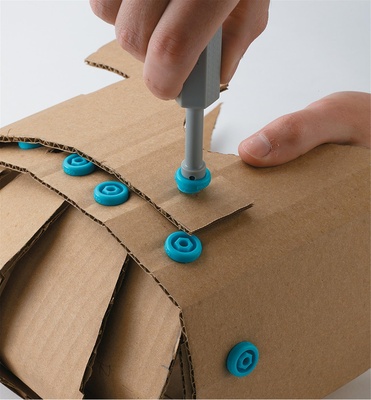
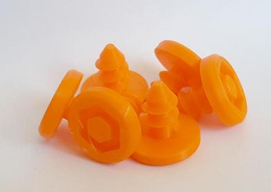
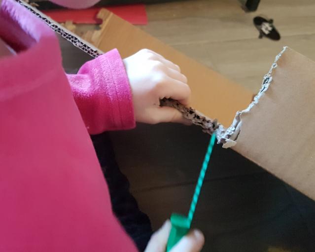
A while ago I stumbled upon Makedo, which offers awesome kits of screws & tools for children to create stuff with cardboard: a safe saw, big chunky screws, a key and a pointy bit to punch holes. Simple enough, yet a fairly cool activity for my kids to do, either with us or in autonomy.
But first I will have a bit of fun of my own, as this is a very good excuse to do some CAD, so let’s warm up the 3D printer and see if there already exists some open models we can tweak. I found a few things, and settled on this set as a starting point.
Because here we start with a mesh from the STL file, I won’t use FreeCAD as I’m vaguely used to, but I will try using Blender directly.
First things first, the add-on
Because we’ll want to produce valid STL, we must use the appropriate 3D‑printing add-on to check our files, otherwise the slicer will produce garbage. Fortunately, that add-on is shipped with Blender directly, so all we have to do is go to “Edit” -> “Preferences” -> “Add-ons”, search for “print” and check “3D‑Print Toolbox”. We can close the window.
However, the toolbox is really hidden… Look for a small arrow at the top right corner of the viewport:
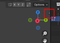
Click & drag left to reveal a toolbox (magic!), then select the “3D‑Print” tab.
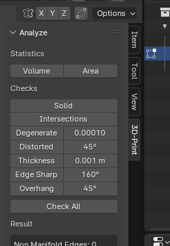
We’ll use that “Check all” button after each complex step to fix our model along the way.
A few guidelines to follow
During this project I did quite a bit of experimenting which I won’t detail entirely. In the following sections you’ll find a summary of a few interesting steps. However, here I compiled a few guidelines that I found useful:
- Don’t trust Blender to keep your model valid, it won’t! Check it regularly, clean it as you go1.
- Temporarily keeping non-manifold edges resulting in missing faces is OK or even desirable, if you do so to avoid later intersections.
- Non-flat faces are simply solved with “Triangulate Faces” when necessary. Use within reason.
- Bad Continuous Edges seems to have to do with normals. Select all, then go to “Mesh” -> “Normals” -> “Recalculate Outside”, this gets rid of the problem.
- Other issues are either solved with automatic vertex merging (see below), or with manual editing of the geometry to make your model one single solid again.
- Manual cleaning is often necessary. Make sure your model stays simple, remove spurious edges or vertices.
- Use vertex merging when possible to keep the model simple. Use the “By distance” merge to automatically clean up some obvious issues, check the bottom status bar to see how many vertices are affected.
- Because we work with meshes directly, it’s not always trivial to edit parameters after the fact. For example, making something bigger might completely mess up connected edges. In these cases, it’s way less painful to roll back and do again.
- Because of the above point, save often and keep your history! You’ll be glad to be able come back to a clean version, especially as the history in Blender doesn’t go that deep by default.
Do note that I use Cura, which requires clean models to start from. It seems other slicers might be more tolerant of some types errors — I’ve notably had errors in the past with overlapping volumes which are fine elsewhere, but still an issue in Cura as seen in this Github issue.
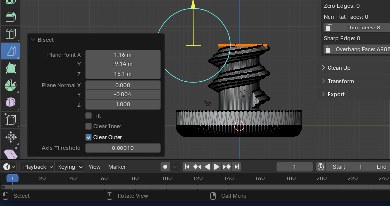
Shortening the screw: bisect
The first issue I want to solve is that the screw in the 3D model is longer than is necessary to assemble 2 pieces of cardboard, so I want to make it shorter.
Let’s open the STL file in Blender: simply create a new empty project, delete the default cube, then “File” -> “Import” -> “Stl” and select the scren file.
At the top left of the viewport, change “Object mode” into “Edit mode”, so we can work on the mesh.
We can cut the screw halfway using the Bisect tool:
At this point we could recreate the top cone.
Fixing the screw: boolean intersect
However, further testing of the screws reveals that the tip of the thread is too large and requires a lot of force or twisting around to properly get in the cardboard. Normal screws avoid that with a cone-like shape, so instead we’ll cut a shape in our screw to both make it shorter & more conical at the same time. To do so we’ll use a boolean operation on the objects with “Intersect”, to instruct Blender to cut our mesh so it stays inside another mesh.
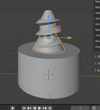
First, let’s create our bounding meshes with a cone and a cylinder, as separate objects. Go back to object mode, then “Add”, “Mesh”, “Cone” or “Cylinder”. You’ll end up with something like this:
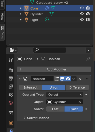
Then, merge these 2 new objects into one with a first boolean operation:
- Select the cone.
- In the “Properties” panel, find the “Modifier” tabs.
- Click on “Add Modifier”, “Generate”, “Boolean”.
- Select “Union”, then in the object field enter your cylinder.
- Apply with Ctrl+A (the “Apply” action is, again, hidden in the combo-box menu right above the “Intersect / Union / Difference” selection buttons).
Note: it might do to simply join the two meshes, but I’m not sure the later Intersect operation would work properly.
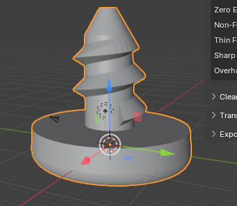
Once applied, the result is stored in the current object, but the cylinder object still exists and overlaps: delete it.
Next, we’ll do the intersect:
- Select the screw object.
- Similarly, create a boolean modifier with “Intersect”.
- Select the bounding object (called “Cone” even if it’s not a cone anymore).
- Before applying, if you want to check the results, you should hide the Cone object.
- Apply, delete the cone object, and voilà!
Use the 3D‑print toolbox’s “Check all” to make sure there are no issues (overhang faces are usually OK, your slicer will be a better judge of that), but it should be OK as we only removed geometry.
Finally, save your model for future reference, export it as STL, and print away!
The key
Similarly the key isn’t perfect:
- I find the punching tool too blunt, which is good for safety, but it requires too much force. It is also too thin, and the resulting hole is too small to fit the screw.
- The 90° edges make it a bit uncomfortable to hold.
- I don’t see the point in having through holes, they probably make printing slower and again, 90° edges.
Cleaning up the pointy side of the key
First, let’s clean that side:
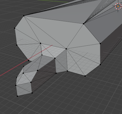
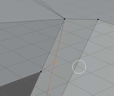
Using the selection in vertices mode, I removed everything but what is stricly necessary to make the edge again:
If we use “Check all” at this stage, we’ll have a few non-manifold edges: our model isn’t solid anymore. Don’t create the missing face! if you do, it’ll intersect with the rest of the model and you’ll have to remove it afterwards.
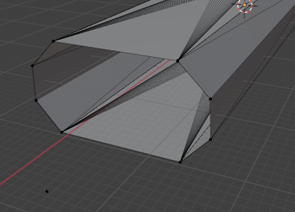
Spin: extruding a round side
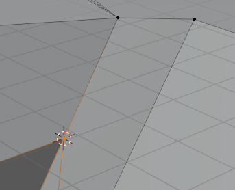
Now we’ll extrude a half circle. First we must define the center of the spining extrusion:
- Select the 8 vertices in view.
- Shift-S: “Cursor to selected” to place the cursor at the center of the selection.
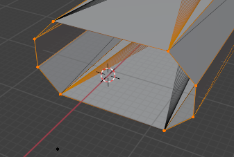
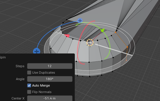
Now for the extrusion:
- Now select only 4 vertices from one side
- Select the Spin tool
- Make the angle 180°
At this point, let’s check our model with “Check All”. 3 intersect faces! What? Manual cleaning is required:
- Select all vertices with “A”.
- Select “Mesh” -> “Merge” (“M”), then “By distance”.
- On this model, a distance of 0.1m is necessary.
- The status bar should indicate that a few vertices are merged.
Check the model again: the issues are solved. Phew, we dodged a bullet here.
Our model isn’t air-tight yet. Select all vertices in the hole above and press “F” (“New face from vertices”). Do the same with the bottom hole.
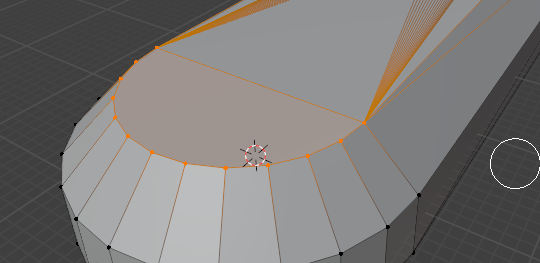
“Check All”: all good!
Bevels
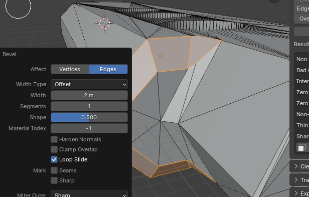
A simple way to make the edges less sharp is to use the Bevel Edges tool.
Use the edge selection mode (see the 3 icons at top of the viewport, next to the “Edit mode” combox box to change between selection modes) to select the edges on one side of the key side.
Use the bevel tool, and select the desired width:
Check your model again. Horror! Again, merge vertices by distance, this solves most issues. Non-flat faces are simply fixed by selecting them (click on the “Non-Flat Faces button”) & triangulating (“Ctrl+T”)
Boolean union: cleaning up required
As we did before, we can add back a pointy bit by creating a separate object and merging it with a union boolean modifier.
However, I found that this operation often resulted in redundant geometry or faces, creating problems with the model. Sometimes cleaning up is as simple as automatic vertices merge, or deleting a few faces, but oftentimes simplifying the geometry manually is required.
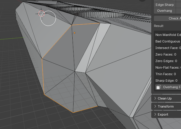
Thankfully, at least when working with low-poly models, that’s not too hard. Let’s take the example below where we have a redundant vertex we want to remove.
We could simply delete the vertex & recreate the face from the vertices around, but it is usually less cumbersome to manuall merge the vertex with another one. Let’s say we need to merge it with the vertex at the lower left corner. We have to:
- Select the destination vertex.
- Move the cursor there with Shift+S then 2 (“Set cursor to selected”).
- Select both vertices, press M to merge, and select “At cursor”.
Rince and repeat as necessary.
Separating part of the mesh into a new object
One final thing I learned was while trying to edit the resulting form, specifically the pointy bit I had merged was too thin. If you’ve read my guidelines above, you know I should have restored a previous version and started from scratch but I persisted.
Notably, at one point it looked like this:
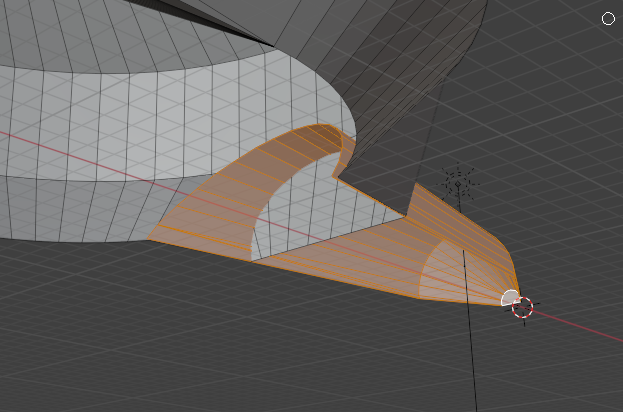
Everything we see here belongs to the same mesh. Must we merge all these vertices by hand? Thankfully, no. Instead, we can:
- Select all faces from our disconnected pointy bit as seen above.
- Press P and use “Selection” to separate the bit into a separate mesh.
- Make both models solid by adding the missing faces.
- Use a Union boolean modifier again to merge the objects properly.
Phew!
The results
I found that after a slight learning curve Blender was perfectly usable in this context, at least on low-poly models since much manual editing is required. It’s also entirely possible that there are more effective ways to do what I did. In any case, the software certainly went a long way since its early days, and I remember a very different experience with its UI years ago.
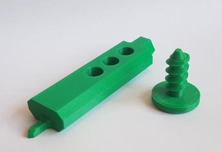
In the end, I created 3 new objects:
- I made the pointy bit into its own tool to have two sides with different sizes.
- The key doesn’t need a pointy bit anymore, and it feels better in the hand like this.
- I created a saw that is somewhat good enough for cardboard, time will tell if it is really useful.
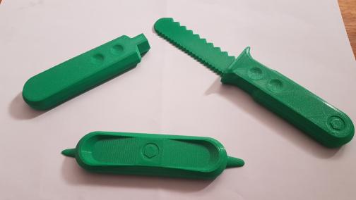
The set can be found on Printables.
-
Channel your inner Irish mother: Foil Arms and Hog on Youtube ↩