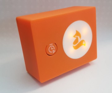
I recently set out to build a 2-minute timer from scratch, by designing and 3D-printing a box and the simple electronic circuit. The final result look like this:
In this article I’ll describe the details of the project: the design choices and questions to be solved.
First design ideas
I wanted the timer to have:
- A button that provides a satisfying click, nothing mushy
- A blinking light
- Some logo or simple image that would show when lit up.
I also had multi-material printing with a single extruder and manual filament changes in mind: I had tried before with PrusaSlicer but the results weren’t great without a prime tower. I recently switched to OrcaSlicer, and wondered if what would work.
I also knew I could make the circuit simply based on 555 timers, and I had purchased a few a while back but never got to play with them yet.

In the end, while it is a very simple object on the surface, it provided just enough depth with fun questions to solve at every corner, making for a very satisfying project I could complete in a few week-ends.
The 3D model
With that in mind, time to open up FreeCAD. If there’s anything I’ve learned about 3D-printing your own stuff is that you have to test absolutely every detail you solve.
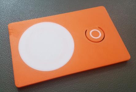
The front panel
As mentioned above, I wanted to use multi-material because it’s fun. I started with the following print:
I had 2 issues:
- The prime tower was huge!
- The printer made awfully big blobs on the prime tower, which would get in the way in later layers and would risk damaging the printer.
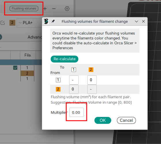
The prime tower size was solved with limiting flushing volumes:
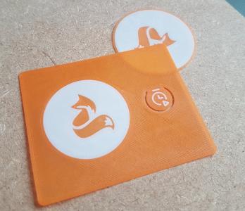
I resolved the second issue by writing a crude post-processing script (available here on github) to identify suspicious extrusion value and reduce them to 0.
With that out of the way, and a few other prints to get the first layer just right (had to re-calibrate recently), we’re good to go:
The ligthing
Next up is testing the lighting with some LEDs.
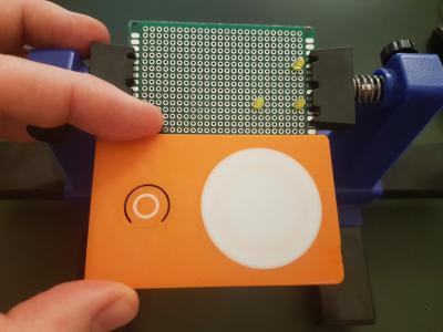
Putting the LEDs right behind the white, .4 mm-height disk doesn’t look pleasing: the light isn’t well distributed and too sharp.
Instead, I tried printing some form of diffuser, and hold it at about one centimeter from the front panel.
The result is dimmer, but nicer - this is what we can see in the picture at the top of the article.
Using screws
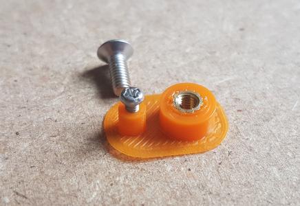
We need two sets of screws: one to hold the PCB, and the other to close the box. For the former, I decided to use simple M2 screws I had lying around, and screw them directly into the plastic. For the box though, I wanted to be able to open and close the lid easily, so I resorted to using screw inserts.
Again, instead of printing the whole model and getting it certainly wrong, I opted to print a minimal test, and fix issues there.
The back panel
I wondered how I would hold the batteries. I have a few battery holders for 2 AAs, and decided to use them directly as-is instead of designing my own and wasting time there. Still, they represent most of the box’s weight, so they must be fixed and ideally close to the bottom.
As a first simple solution, I tried to print a cradle and see how well that would hold:
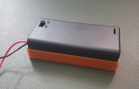
And it fits perfectly, is easy to remove but still holds well. Perfect!
Fitting it all with the PCB
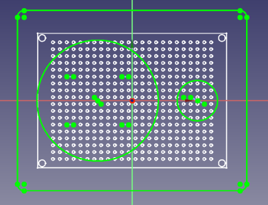
As I experimented with the PCB, I realized I wasn’t too sure where I could place the components. Moreover, to print the LED diffuser or PCB mounts, I must know the exact placement of components with regard to each other.
What I ended up doing was creating a sketch with holes spaced by 2.54 mm (.1 inch). I printed it on paper for reference, and fixed the dimensions until they fit the real object I had.
Then, using this sketch as reference throughout the design, I could place my elements properly and make sure I would get a fit on the first print.
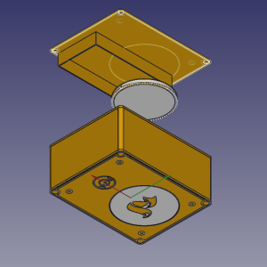
Final design
This was my most complicated object with FreeCAD yet: a combination of Sketches, Part Design workbench, and Part workbench for boolean operations where needed.
It might be interesting to talk a bit about FreeCAD here: I’m incredibly grateful this wonderful piece of open-source software exists, I feel I can learn it and rely on it in the years to come, which is worth a bit of a learning curve.
That being said, there are some annoying bits that just hurt the workflow:
- Editing the PCB sketch, with its thousands of constraints, was super slow (think 20-30s per operation). However, once closed, it didn’t slow down anything anymore, so FreeCAD was smart there.
- I created a first sketch for the front plate, which I then used as a reference for later sketches. Going back to the first one and adding fillets wrecked havoc on the references, and I had start from scratch. Fillets are a pain to reference, to, so it might be smart to wait until the end and apply them in the Part workbench instead.
- Reusing sketches for multiple shapes is sketchy (pun intended): you can’t select part of the sketch for the operation, so you have to create a new sketch, reproduce a similar shape referencing the source sketch manually, then use that.
- When using a sketch as reference for further shapes — which as we’ve seen with the previous item, you end up doing a lot — there are multiple ways to combine references (“the circle here is centered on that circle in the reference sketch”) and local constraints (“and it touches this line that already exists”) to make a viable sketch. However, some are better than others: you might end up with partially redundant constraints, or suddenly with redundant constraints which aren’t obviously solvable unless you go a completely different route. I think this is where I spent most of my time in the tool, finding new and minimalist ways to use the reference sketch, and use local constraints as much as possible.
- Finally, it did crash a few times, which doesn’t feel nice, but usually recovery takes you but a few steps back so that was fine.
In the end: I save often, I save copies, I learn along the way, I’m grateful of what it enables me to do. But I probably would not use it in a professional capacity.
Anyway now we can print it all, and look at the circuit.
The circuit
Nothing too fancy here:
- A pre-built DC-DC boost converted to reach 5V from 2 AA batteries.
- A 1st 555 timer in monostable configuration to count up to 2 minutes.
- A 2nd 555 timer in astable configuration to flash the LEDs.
- A button to trigger the whole thing up.
- 4 LEDs & their current-limiting resistor.
The 555s are used in cascade, with the output of the first being the second’s VCC. That incurred a noticeable voltage drop, but wasn’t a problem in the end.
The 555 circuits look like the following:
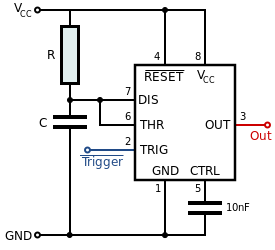

I won’t dwell on how these work, these circuits as extremely common and there are far better resources than my poor explanations, starting with the Wikipedia links above.
Being an analog circuit, the values of resistors and capacitors depend on the desired behavior. The formulas aren’t too hard, but you can also use a calculator such as this one. Still, I found that the values are just a starting point: you need flexibility to change values in your circuit to properly set it to your desired values.
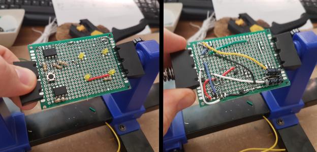
I built the circuit in stages and checked it along the way. That was a good idea, as I messed up the monostable part and it took me a bit to realize I had mounted the 555 backward… Ahem. Also, I had to change the resistor values I used as the timing I got where different on the protoboard than they were on the breadboard, and I wanted it to be just right.
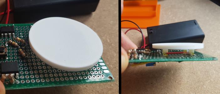
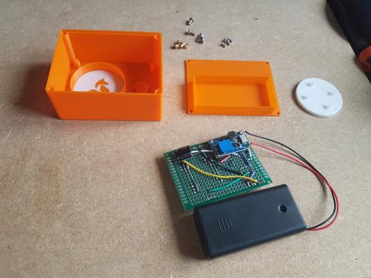
Moreover, I had to mind the depth of my assembly, and wanted to minimize it: for this reason I located both large capacitors in a corner of the PCB, where they wouldn’t get in the way of the battery holder.
An hour or so of soldering and tinkering later, and we have a functioning circuit:
Final assembly
And now for the big moment!
During testing, I noticed quite a lot of light leakage to I added a bit of aluminum foil to the light cover:

Note the protrusion under the plate’s button to make it reach the actual button on the PCB. The result feels right, with very little space between the two, and a light press immediately produces a nice click.
The assembly went well and the first print fit well! 2 small issues:
- I must have forgotten to update the holes for PCB screws in the PCB mounts, and had to drill them to size.
- The space between these mounts was ever so slightly too large (by about .5-1mm): it did fit but barely. Maybe my (paper) printer’s scale isn’t perfect, and the adjustments I made weren’t necessary after all. I’ll have to check that next time.
I’m really happy at how the project turned out: fun questions to solve, learned a few things along the way, didn’t drag out for months on end, and the final customer got its tooth-brushing-time timer delivered swiftly!
There might be more on this subject later on, as I ordered a bunch of ATtiny85…