This article is part 2 (see part 1, part 1-B, then part 3) in a series were we try to build a MIDI instrument from a bunch of SN76489s, which is the sound chip used in the Sega Game Gear, the BBC Micro, the Neo Geo Pocket and quite a few others.
At this point in the project, we have reliable communication with one SN76489 chip on the breadboard and some form of sound output. In this article, we’ll make it play its first note, control it from a computer, and start improving its musicality.
Playing notes
First we need to solve a detail we’ve overlooked in part 1: how do we specify a note’s pitch?
According to the specification, we must send a 10-bit number to set the frequency. That number won’t be in hertz, but rather a division of the input clock: with the clock’s frequency, the 10-bit number passed as “Tone frequency” and the resulting note’s frequency, we have:
This being limited to 10 bits means there is a limited range of frequency that will be available to us, and for two reasons:
- First, the ratio between lowest and highest frequency will be 1023
- Second, in the low region (higher frequencies), the jump between 2 consecutive values will result in huge jumps in resulting frequencies, making it hard to get a precise pitch. The higher the note, the bigger the step, the more out-of-tune it will be.
To find a good balance, let’s calculate the target for the entire MIDI notes range. Moreover, we need a measure how out-of-tune notes are. For this, we’ll calculate the error the rounding of produces by comparing the error in the obtained frequency with the step in frequency from the previous semi-tone.
Remember that in part 1, we assumed the maximum possible clock frequency for the chip, at 4 Mhz. Let’s start from this clock value and see what we get:
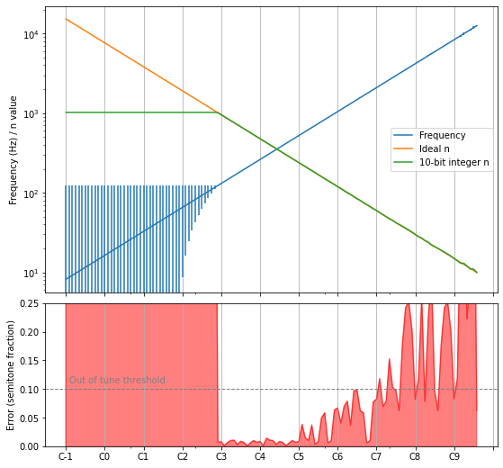
This graph outlines the 3 regions we mentionned:
- To the left, the innaccessible low notes where . The error on the frequency is of course huge.
- In the middle, the valid range with an acceptable error. I arbitrarily set the threshold to 10% of a semitone.
- To the right, the out-of-tune higher pitches. Even though the frequency error is barely visible on the blue frequency curve, the bottom graph shows that it is very hearable.
This balance is not good, because B2 being our lowest note is not very satisfying — going lower would provide much nicer bass sounds. However, if we reach the lowest possible MIDI notes, then the precision error creeps very quickly at ranges we definitely want to use! This 10-bit precision is not very good, and it seems other chips do better in that regard: the AY-3-8910 is a very similar chip, but has a 12-bit divider.
In the end, I settled on E1 being my lowest note. Highs get a little out of tune but that’s bearable. We reach this by applying using a timer step of 5, giving us a clock frequency of 1.33 MHz.
Here are the error graphs for the initial 4 MHz situation, the corrected 1.33 MHz clock, and a 4 MHz but with 12 bits of precision of the AY-3-8910 which we wish we got:
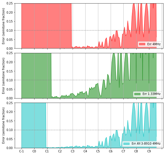
In the middle graph, we see we get about 4 usable octaves, starting in the middle of octave 1 up to the middle of octave 5. Starting octave 4, it will start to sound a tad out of tune, but that should be acceptable.
Setting up MIDI
The simplest way to go about controlling this from a computer is to use the MIDI protocol.
What is MIDI
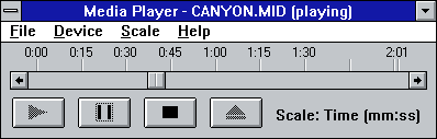
You’ve probably heard about MIDI at least in the form of .mid files: lightweight files that can be played, and the ouptut is often a very computer-y sound, but quite comprehensive with various instruments available. If you’re old enough, you might even fondly remember the good old 🎵 Canyon.mid!
These .mid files contain MIDI commands such as notes with pitches for instruments, or modulation values. The instrument “patches” (instrument sets) are standardized, and nowadays every system under the sun can generate the appropriate sound for these commands.
These files are now a bit obsolete, because size & compute power is not an issue anymore. However, the protocol itself was initially designed to communicate with external instruments, and that’s where it still lives and thrives.
The protocol even got updated recently with new additions such as MPE (midi polyphonic expression) that basically allows more control over individual notes. You can see an example of Jordan Rudess demoing such a keyboard. I especially love how the vibrato works on this.
MIDI with Arduino
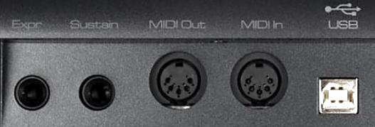
MIDI is well-supported in the Arduino environment, either through the usual MIDI serial connection or via its more modern USB layer. Because I don’t have a USB-MIDI adapter, we’ll go for the USB solution with the library MIDIUSB.
This library does not work on my old trusty Arduino Duelaminove, because it requires control over the actual USB connection (whereas mine is using a USB-serial chip). Instead, we can use an Arduino Micro or one of its clones.
Receiving MIDI events over USB is incredibly easy to setup, with the basic skeleton looking as follows:
#include <Arduino.h>
#include "MIDIUSB.h"

void setup () {}

void loop() {
  midiEventPacket_t rx = MidiUSB.read();

  switch (rx.header) {
    case 0:
      break; //No pending events

    case 0x9:
      noteOn(
        rx.byte1 & 0xF,  //channel
        rx.byte2,        //pitch
        rx.byte3         //velocity
      );
      break;

    // [...]
  }
}
Note how the library is rather low level when it comes to the protocol itself: you have to know byte values and how to extract the message’s content. In reality, there aren’t that many different types of messages, and you can use the MIDI 1.0 specifications for that.
The next step is to connect these noteOn and noteOff functions to the proper output for our SN76489 chip. MIDI provides up to 15 independent channels, so we can easily control our 3 square oscillators separately.
An now we can connect the thing to your computer, fire up VMPK, and you can test individual channels & notes.
At the risk of making this section read a bit like “draw the rest of the owl”, I won’t get into much more details about the plumbing because it is not that interesting to talk about. In any case, the code is in a public repo at midi2sn76489. Note that at some point in the project I switched over to PlatformIO for VSCode, because I don’t really like the vanilla Arduino environment for more than trivial sketches.
A first tune
For the demonstration here, I use a simple setup where aplaymidi will ouptut the commands from a .mid file to the MIDI hardware:
> aplaymidi -l
 Port    Client name                      Port name
 14:0    Midi Through                     Midi Through Port-0
 24:0    SparkFun Pro Micro               SparkFun Pro Micro MIDI 1
128:0    VMPK Input                       in
> aplaymidi -p 24:0 totoro.mid
And the output sounds like this:
That’s one heck of a milestone!
Envelope
Now that we can play notes, the next step we can take to make it sound a bit more natural is to implement an envelope. This is to mimic real-world sounds, where the amplitude (volume) is not constant for the whole note’s duration.
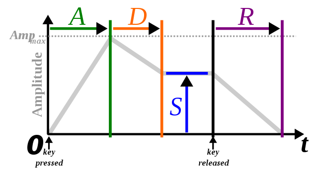
ADSR
A commonly found envelope model is ADSR for Attack, Decay, Sustain, Release:
Sustain is measured as a fraction of the amplitude, while the other parameters are time based.
In this model, a piano note would have a very short attack and decay, a reasonable sustain and a short release when the key is released (assuming no sustain pedal). Note this is an approximation, as a piano note cannot be sustained forever - we would need the sustain phase to be a downward slope but that’s not part of the ADSR envelope.
On the other hand, a bowed instrument played in a mellow fashion has a longer attack, no decay, a high sustain, and a moderate release:
You can also play bowed strings staccato, with much shorter attacks — a drum kick would have a very similar envelope:
As we can see, it’s a simple model but versatile enough for our needs.
Implementation
Again, the plumbing itself isn’t that fascinating: the volume must change with time, following various slopes. Let’s highlight a few notable details though:
To implement the envelope, we must control the volume of the oscillators with the 4-bit register Attenuation — as we’ve seen in part 1, this register goes from 0 (maximum sound amplitude) to 15 (channel is off). This resolution is not great, especially when we’ll want to control quiet sounds, but we’ll have to do with it.
Moreover, we should take a look at the MIDI specification a little closer:
| 1001nnnn | 0kkkkkkk 0vvvvvvv |
Note On event. This message is sent when a note is depressed (start). (kkkkkkk) is the key (note) number. (vvvvvvv) is the velocity. |
As you see, incoming notes carry their pitch along with a parameter called velocity — this is basically the strength of the note, or quite litteraly the velocity of the keyboard key.
Not knowing any better, I decided to use the velocity paramater as a factor applied to the envelope’s amplitude, so both the attack peak and the sustain are impacted. It works well enough.
Here is the same tune as above, this time with the ADSR envelope and velocity implemented:
Drums
Ah, drums. There we are. The SN76489 is a bit poor when it comes to drums. Where other chips get away with the situation by providing a crude PCM channel, we are limited to one noise channel.
Noise channel
First, we can choose which type of noise we use: either periodic or white noise. Then we are provided with 3 basic input frequencies: , , . These options sound like this:
In my tests, I found that I needed to use higher frequencies than what was provided, especially to reproduce something like a hit-hat. Fortunately, the last option is to use the 3rd oscillator’s output as an input frequency to the noise channel. This means we can essentially sacrifice one oscillator output for better noise control. Combining this with envelopes, I got to the following set of sounds:
That’s… let’s go with “charming”? Creative people would probably squeeze way more, but so far that’s the best I managed to find. Here is what it sounds like in context1:
You might be surprised that I would willingly sacrifice a whole tone channel. However, you’ll see in part 3 that this is an acceptable compromise because we’ll have tone channels to spare.
Kick
But still, can’t we do juuuust a bit more? Famous last words
Looking around I learned that certain games targetting this chip emulated PCM playback2. I assume that is how they produced that “SEGA” sound at the start of the console. However, they seem to use a mode where a frequency parameter of 1 would keep the output pin high, which effectively does not work on my version of the chip3. Moreover, while that may be one way to get more diversity, why use the chip at all when the arduino has a few output pins available? I feel that this option would be pushing the project’s boundary a bit too far, so I won’t go that way.
Still, I found that the thing I missed the most was a punchy kick sound.
Here’s what this sound looks like:
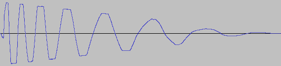
Couldn’t we mimick this with a single square wave? We can imagine reproducing this by carefuly controlling one of the oscillators. Before we commit to coding, let’s simulate that first.
We’ll iterate through a frequency range going from 150 Hz to 20 Hz. To keep this simple yet smooth, we’ll wait for a full period before changing to the next frequency:
T = 0.25      # Duration of sample, in seconds
samples = []  # List of sample points, that we'll use in the Arduino code

t = 0
while t < T:
    amplitude = curve(1, 0, T, t)
    freq = curve(150, 20, T, t)
    period = 1 / freq
    samples.append((freq, amplitude, period))

    t += period
In the above code, curve is simply a function that will return a value between the first 2 parameters based on t, in a 1/x-type curve.
We can then create the actual PCM data based on this, and output that into matplotlib and IPython.display.Audio:
import IPython.display as ipd
import math

sr = 44100        # sample rate of the output PCM audio data
pcm_samples = []  # List of PCM samples

for freq, amplitude, delay in samples:
    for i in range(int(sr * delay)):
        t = i / sr
        value = math.sin(2*math.pi*freq*(t))
        pcm_samples.append(amplitude * (1 if value > 0 else -1))

ipd.display(ipd.Audio(pcm_samples, rate=sr))
plt.plot(samples)
This made it easy to experiment a bit with various curves and frequency ranges. Below are the results I settled on:
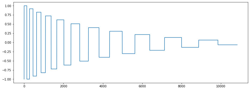
That sounds like a very distorted kick. It’s not exactly was I was going for, but it’s going in a very usable direction, I like it!
At this point the Arduino code is really not suited for this kind of “sample” (or rather, controlled) playback, but hacking the implementation is quite easy:
- We don’t need to update at a rate of 11025 kHz or more like we would if we were playing samples — we simply have to change the oscillator’s frequency & volume periodically. We already have facilities in place for the envelope, we just need special cases.
- We’re already sacrificing oscillator 3 to control the noise channel anyway, so we can use it for playback of this kick sound (and mute the noise channel while doing so).
- We can easily store the data in the Arduino’s flash.
With this new sound under our belt, let’s change our little loop above to use this kick instead:
I’m pretty satisfied with how this sounds.
Some music
With everything we’ve built so far, it’s time to have some fun and make some music! This will also drive new features as we try to make it sound interesting, as there are a few obvious things missing.
I experimented with multiple DAWs & other software, including REAPER and Rosegarden. For now I settled on the 8-track edition of Bitwig:
- It’s quite straightforward to get the live sound output from the hardware instrument back to the DAW and apply filters to it, then output it back to your sound card. Plus, finding out the latency between MIDI & sound input is just a click away.
- The UI is quite easy to discover.
- The separation between individual loops on one side & general sequencer on the other felt like a natural workflow.
- Arpeggiator!
- Finally, it’s the only tool that silently reconnected to my MIDI hardware after each of the numerous firmware updates — every other tool required some manual action after uploading a patch to the Arduino, which was seriously cumbersome.
Starting a cover
I want to start small and have fun quickly, so let’s cover some songs. That, and I don’t know how to make music, so, you know.
For my first dab at this I copied a fun track from the Modern Vintage Gamer channel. Here is a screenshot of the projet:
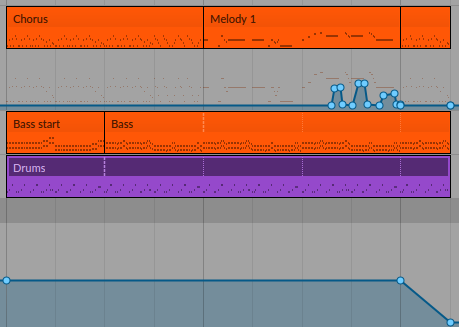
And it sounds like this:
That’s almost usable now! The timbre of the melody long-held notes sounds a bit flat and boring, while in the original there is a nice filter on top to make it interesting. We’ll make this better4.
What’s next
In this article we’ve really brought our project forward, from making random noises up to something usable: we’ve sent the first notes, integrated the MIDI protocol, implemented a basic ADSR envelope and programmed some drums.
Theoretically though, at this point the chip is still sitting on a breadboard. In part 3, we’ll make something more permanent, integrate multiple SN76489 chips together, and build a case for it all. Finally, we’ll implement more features. See you then!